In a fast, accurate and user-friendly way, our coupling software performs the selection of rigid and flexible couplings that connect shafts of machinery.
The programming logic is developed according to the fundamentals of mechanical transmissions, combined with specific rules of the manufacturers, and with a database containing the technical specifications of each coupling size and type.
Select rigid and flexible couplings quickly and accurately. Our software merges mechanical expertise with a comprehensive database, transforming coupling selection into a remarkably intuitive process.
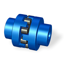
Power transmission couplings are basically manufactured in two different categories namely rigid and flexible.
Flexible couplings are those with a greater variety of types, but all are produced in a wide variety of sizes, capacities, and materials to suit any industrial application.

For the selection of the appropriate coupling, the programming logic guides the software user step by step.
A design wizard helps the user through the data input process and provides explanations about the meaning of each design requirement and available configuration options.
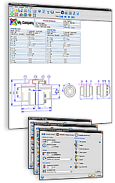
In a highly organized, flexible and friendly environment, the user establishes the design requirements and the software performs all calculations and analysis necessary for sizing of the coupling:


Since couplings are often assembled on shafts of industrial electric motors, the software has an extensive database containing data of electric motors from around the world.
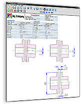
For the assembly of the coupling, it is almost always necessary to machine the holes for the driver and driven shafts.
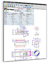
The coupling software automatically generates CAD drawings of the fixing elements, with all dimensions and tolerances.
Flexible couplings allow some degree of misalignment between the driven and driving shafts.
The software shows data and drawings related to misalignment capacity of the coupling selected in three different directions:
In some cases, misalignment limits can vary according to the operating speed of the coupling.
In other cases, misalignment limits can vary among themselves.
If so, the program plots the corresponding graphs:

Once the coupling has been selected, the software automatically generates all the engineering reports, datasheets, charts and CAD drawings in several standard paper sizes.
The display and printing of reports use a WYSIWYG (What You See Is What You Get) interface:
All of these documents can be easily customized, printed, emailed or exported to formats like:
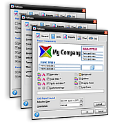
As a result of customer demand for more flexible and comprehensive solutions, the software has a host of configuration options that allow the user to customize it to suit his personal wishes and preferences.


1) Hover over thumbnail to view enlarged image. 2) Click on thumbnail to hold enlarged image in place. 3) Click outside thumbnail to hide enlarged image.

Built with multilingual user interface and an advanced unit converter, our software is fully capable to meet the needs and requirements of any manufacturer in the world, regardless of the volume of its production or the variety of its product range.

This software is intended exclusively for coupling manufacturers, so there is not a version available to individual users.
We make a customized version for each client.
The general guidelines for the implementation of this software are described in the purchasing process of our software solutions.
If you wish to start the purchasing process or request more information about our coupling software, please contact us. We are able to develop a customized and exclusive version for your company.

Ciclo is a technology company that develops software for the design of machines. We take pride in providing top-notch solutions that strengthen our clients' businesses.
Copyright © 1998-2025 Ciclo Software Ltd. All rights reserved.