
Our speed reducer software performs selection of any type of industrial gearbox or gearmotor, according to the technical requirements of the application.
The software analyses characteristics of the driver and the driven machine by considering their operating conditions, such as their speeds, transmission power, output torque, type of load, hours of operating, frequency of starting, reversibility, ambient temperature, and overhung load on the output shaft.
Find the ideal gearbox for your industrial application with ease. Our software analyzes technical requirements and provides users with step-by-step guided assistance.
Manufactured by many companies around the world, gearmotors and speed reducers are available in a wide variety of sizes, capacities, materials, configurations, and mounting positions to suit any industrial application.
These mechanical transmission devices can be basically distinguished by shape of their gear sets, as well as the relative position of their shafts.

For the selection of the appropriate gearmotor or speed reducer, the programming logic guides the software user step by step.
A design wizard helps the user through the data input process and provides explanations about the meaning of each design requirement and available configuration options.
In a highly organized, flexible and friendly environment, the user establishes the design requirements and the software performs all calculations and analysis necessary for sizing of the gearbox:
In transmission systems with variable demand, the use of adjustable speed drives is now common.
Under such circumstances, it is essential that the designer has a broad view of the behavior of the gearmotor to be selected.
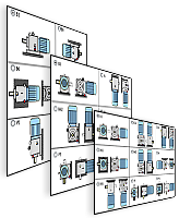
Our software has the most advanced engineering charts with high resolution details, which show characteristic curves throughout the operating speed range.


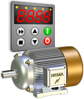
Gearmotor manufacturers must ensure that the motor and gearbox combination will work properly together in a particular application.
For choosing an electric motor that is compatible with the selected speed reducer, the software has an extensive database containing data of industrial electric motors from around the world.
In addition to the design requirements, the software allows the user to set up construction features and choose components for each gearmotor, such as:
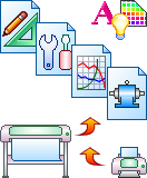
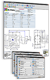
Once the gearmotor or speed reducer has been selected, the software automatically generates all the engineering reports, datasheets, charts and CAD drawings in several standard paper sizes.
The display and printing of reports use a WYSIWYG (What You See Is What You Get) interface:
All of these documents can be easily customized, printed, emailed or exported to formats like:
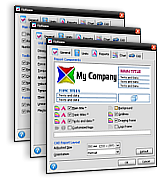
As a result of customer demand for more flexible and comprehensive solutions, the software has a host of configuration options that allow the user to customize it to suit his personal wishes and preferences.


1) Hover over thumbnail to view enlarged image. 2) Click on thumbnail to hold enlarged image in place. 3) Click outside thumbnail to hide enlarged image.

Built with multilingual user interface and an advanced unit converter, our software is fully capable to meet the needs and requirements of any manufacturer in the world, regardless of the volume of its production or the variety of its product range.

This software is intended exclusively for gearmotor manufacturers or speed reducer manufacturers, so there is not a version available to individual users.
We make a customized version for each client.
The general guidelines for the implementation of this software are described in the purchasing process of our software solutions.
If you wish to start the purchasing process or request more information about our gearmotor software or speed reducer software, please contact us. We are able to develop a customized and exclusive version for your company.

Ciclo is a technology company that develops software for the design of machines. We take pride in providing top-notch solutions that strengthen our clients' businesses.
Copyright © 1998-2023 Ciclo Software Ltd. All rights reserved.